I had made Newtonian telescope mirrors before ann two classical Cassegrains of 8inch and 17.5inch aperture. The 17.5inch actually was an original Coulter paraboloidal f4.5 mirror which I wanted to convert into a longer focal length instrument by adding a Cassegrain secondary mirror. That secondary was actually a 5inch mirror in its own right. After a little pause on the topic of Cassegrains I wanted to try my luck at a system that would exhibit the advantages of typical Cassegrain design. A short compact tube and a field corrected for CCD imaging. The first led to a design with pretty steep curves on the glass. The second to the choice of the Ritchey Chretien system among the different types of Cassegrain telescopes.
I designed the mechanical parts in parallel with the optical system.
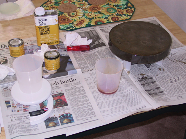
I ordered the mirrors from Newport Lens with pre ground radius in the primary. The radius is 1320 mm or an F-ratio of 2.6. The sagitta of the 10inch diameter glass is about 6mm. I cast a grinding tool from 'Pourstone' cement. To pour the tool I made a card board ring around the mirror, added a layer of kitchen wrap and poured the mixture into this mold. After it had hardened the tool already had a pretty good copy of the radius of the mirror. The tool took quite a while to completely dry out. I let it sit on the balcony in the sun for a few days to make sure no moisture was left in it. I then covered it with epoxy resin to waterproof it.
In the still wet epoxy of the curved side of the tool I laid the ceramic tiles used for grinding. They very nicely followed the curvature already and I decided not to lay the mirror on top of it for further fitting but at the risk of the whole thing getting clued together.
I wanted to grind the primary and secondary in parallel. The idea was that at any given time only one size of grit was floating around the work place. The process seems to have worked well as there are so far no scratches in the optics.
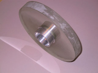
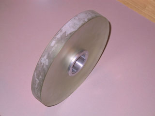
Picture of grinding tool
Grinding started with 220 grit and in less than 1 hour full contact was established between the mirror and all the grinding tiles. Grinding of the secondary mirrors stared at 80grit even before the primary was joining in. As the secondary diameter is about 4inch the required radius was reached in 30minutes. The back sides were also ground and raw polished so that later interference fringe testing could be performed through the back surface
I went through fine grinding the mirrors using grit: 220, 400, 600, 9micron and 5micron. After grinding I wanted to keep the grinding tool available in case I had to redo some fine grinding. I cast another tools from Pourstone and sealed it with epoxy resin. Then a pitch lap was poured on it and polishing began.
Here is a log of the figuring process.
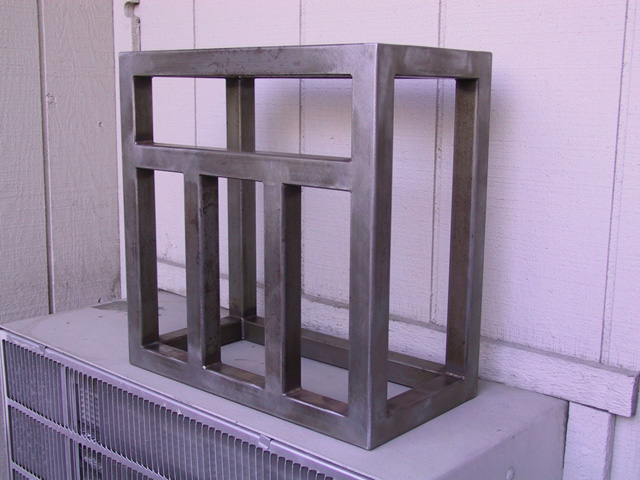
The mirror cell is welded from 1inch square tubing. I can't do that
myself to the wanted accuracy and so I had a steel workshop build it for
me. It turned out very well.
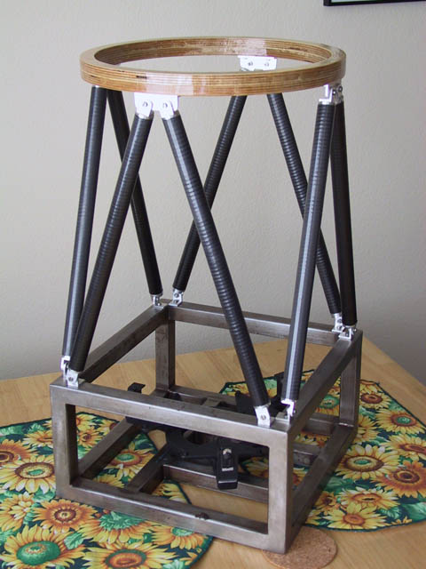
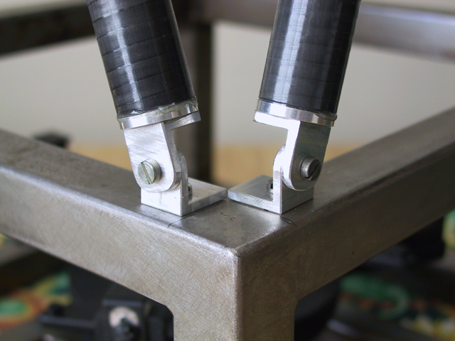
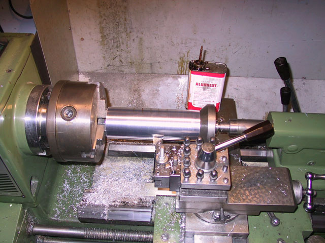
For the truss tube I used 20mm carbon fiber tubing material. This gives a zero thermal expansion to the tube which is critical to keep a stable focus position in the Cassegrain setup. The carbon material itself is too thin to support bolts, so I machined aluminum plugs to glue into the carbon fiber tubes and then be bolted to the steel mirror cell.
Here are a few details for the aluminum plugs that connect the carbon fiber tubes to the mirror cell material.
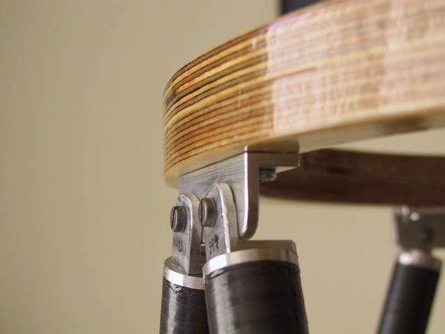
At the top of the tube a plywood ring holds the spider which in turn holds the secondary mirror holder and cell.
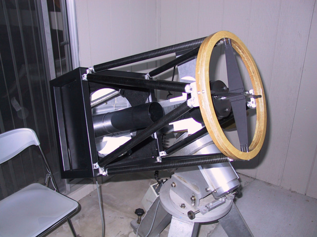
Here is a picture of the complete truss tube test mounted onto the Super Polaris mount.
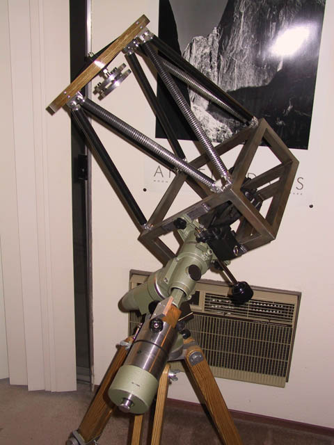
Here is a detail of the extra strengthening bars on the mirror cell. 1/4"-20 threaded holes allow to mount the tube on the Vixen Polaris mount. Ultimately the mount will be a bit too weak for the telescope. But it's OK for initial tests.
Next comes the secondary cell. The cell is built in classical way made of two aluminum disks. One the base plate, the other with the collimation bolts carries the mirror. The springs used are disk springs, which provide better strength than spiral springs and will not allow the collimation to wobble. The cell is mounted to the secondary spider using the central bolt. The lateral motion also allows for adjusting the focus position.
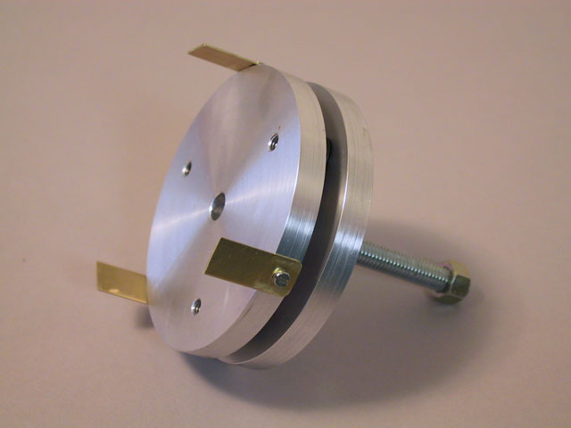
The clamps will be an extra insurance to hold the mirror. The plan is to lock it into place with silicone glue to avoid it moving around.
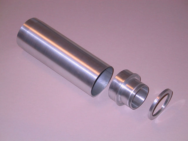
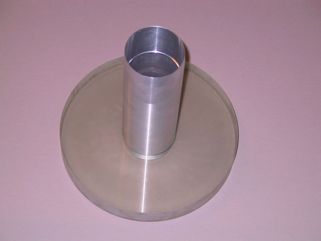
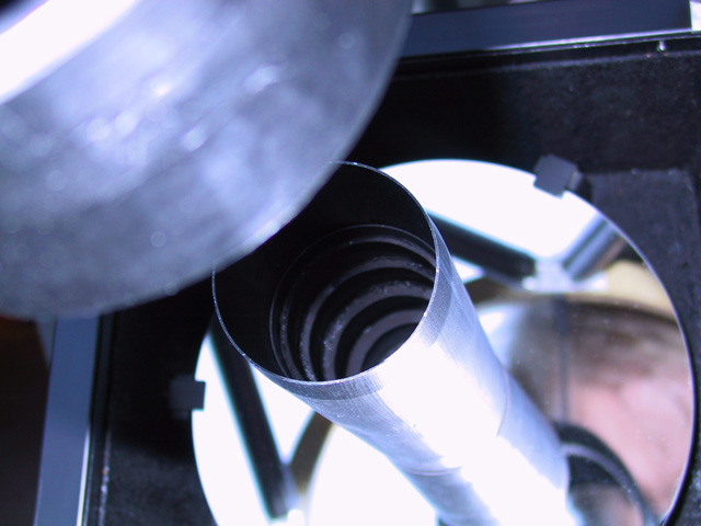
This is the making and assembly of the baffle tube. The baffle tube is held in the hole in the primary mirror by a ring nut.
 |
 |
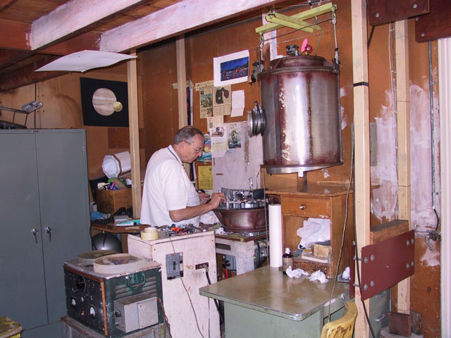
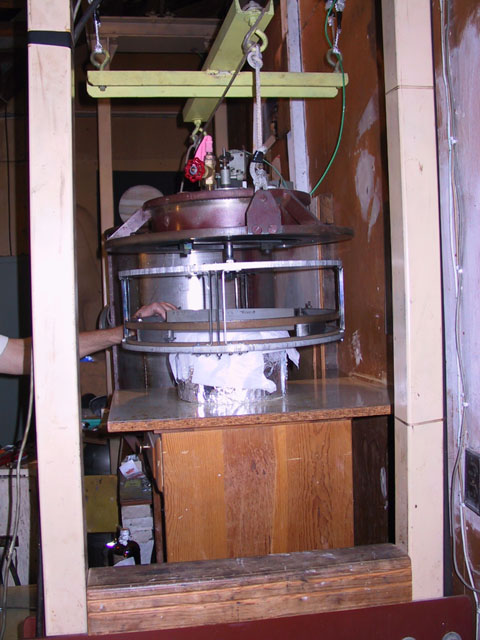
The aluminum coating of the primary was done at 'Alcoat' (Bob Fies).
Here are a few pictures from the process. This is Bob and his vacuum coating
machine. He is loading the machine with pieces of aluminum wire and silicon
oxide for coating.
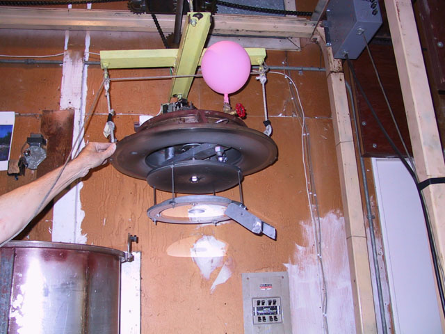
The glass is mounted face down into a holder. In the vacuum chamber it is hung from the top above the evaporating aluminum.
After the coating the mirror emerges with a clean coat of aluminum and protective SiO layer. Bob recommends to let the mirror rest for a few days. He says the coating still gets harder over time.
Thanks to 'Alcoat' for the great work!
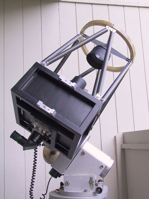
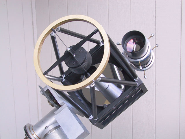
After the secondary was finished the whole telescope was assembled.
The two baffles were mounted.
The primary baffle was very shiny. Card board rings were cut and installed. Although this did not solve the problem for the entire length of the baffle a lot of stray light was removed.
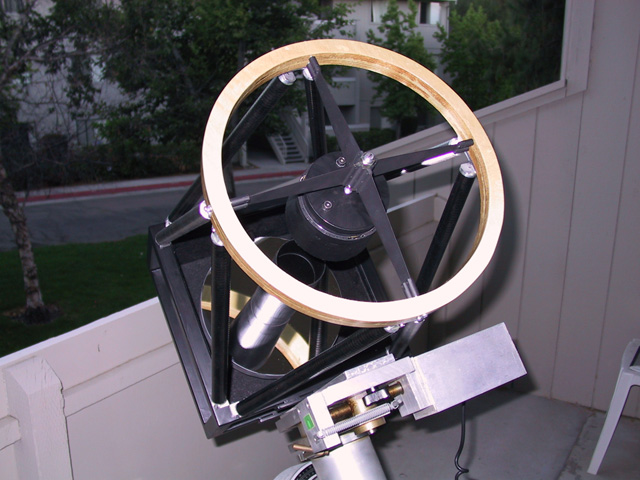
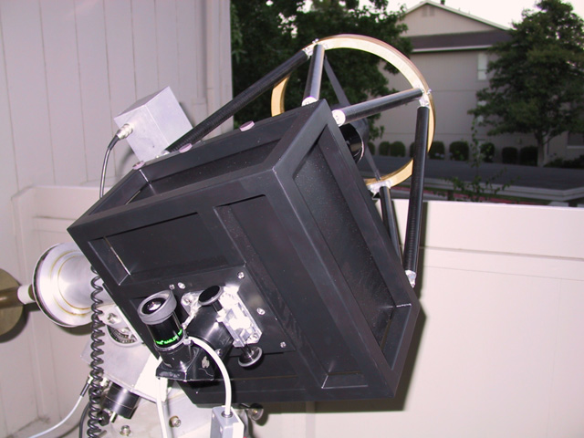
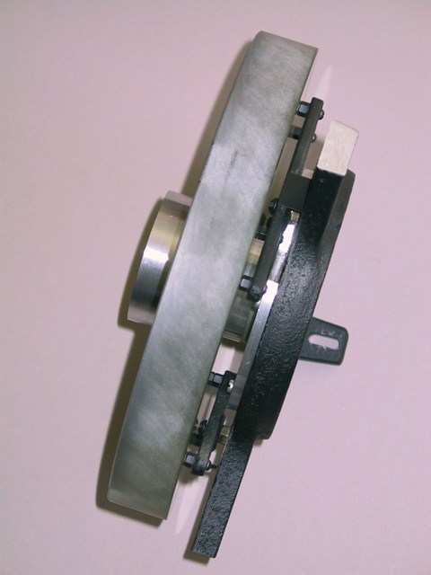
A side and rear view of the finished scope. Next a guide scope mount will be attached to the primary frame. Then CCD observations can begin.
Now add the rings. The tips of the adjustment screws have nylon inlays to avoid damage to the guide scope tube.
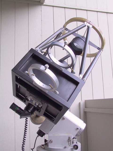
To follow the style the guide scope is a Russian maksutov telephoto lens 1000mm F10.
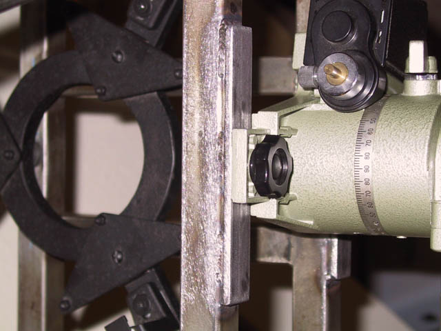
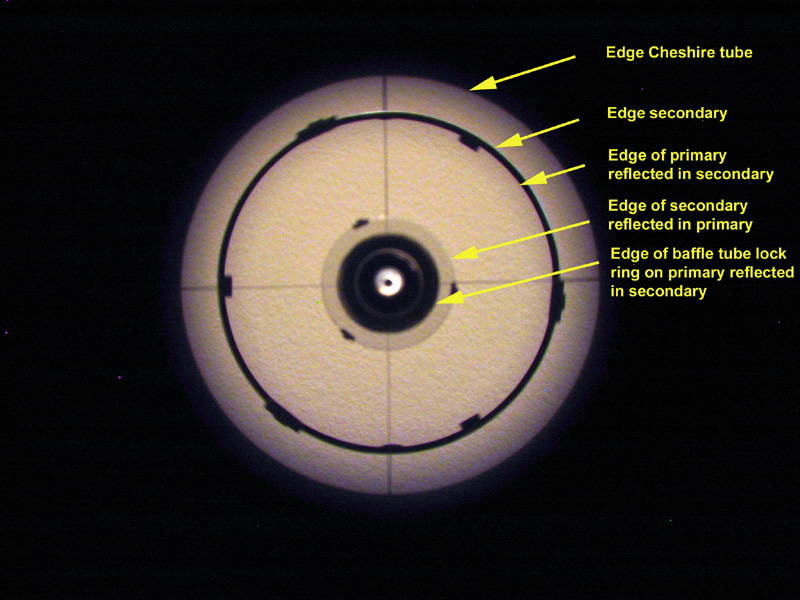
Here is a snapshot on the collimation of the scope during the day
time using a cheshire eyepiece. Collimation is very critical and even when
it looks good in the Cheshire a little bit of fine tuning is required at
night on a star.
I did not like the clamps holding the primary in the first place.
The primary is very sensitive to collimation errors. The little rattling
that I normally would allow it in a Newtonian was compromising collimation
in this fast system. As I was forced to give at least a tiny bit of pressure
to the clamps the figure of the mirror suffered immediately. Those clamps
are just bad. They push on the mirror where it is most vulnerable (at the
edge) and also most important (outer zone). Any resulting deformation has
maximum negative impact!
As this is a Cassegrain the mirror has a hole in the center and the natural idea is to use the hole for support. I had done this totally wrong in the first place. The mirrors was held in the cell by the clamps and the baffle tube was attached to the hole. Thus the mirror was supporting the baffle. The idea for the redesign was to reverse that. The baffle holds the mirror and the clamps are gone!
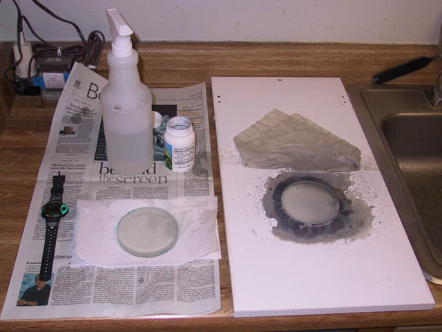
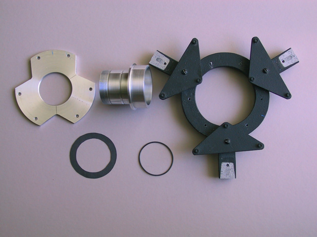
Here are the part. I made a bottom plate (left) to hold the new longer baffle tube (center). Right is the rest of the Novak cell. Below are a rubber O-ring that was supposed to go into the grove in the baffle support and the cardboard piece to cushion the mirror again the aluminum rim of the baffle holder.
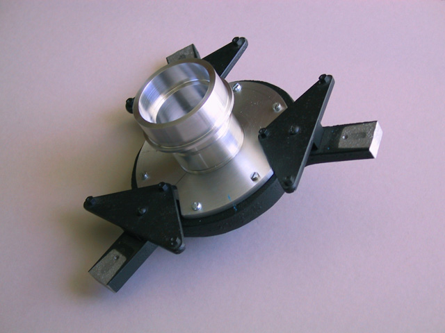
This is how the whole structure looks minus the glass. The mirror is securely held between the cell triangles and the holding rim on the baffle structure. Even if the aluminum is pushing a bit against the glass and the mirror deforms, this is all behind the 4" shadow of the secondary and will not impact the optical performance much.
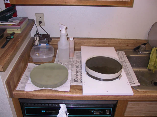
This is the assembled structure with the glass.
The aluminum parts got flat black paint. I also attached the baffle tube to the holder.
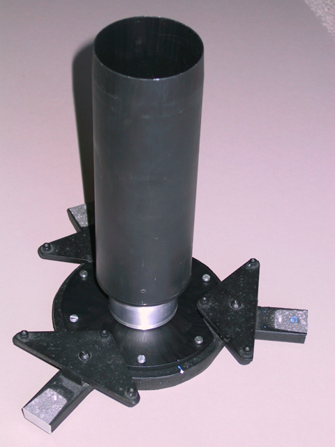
The full assembly is mounted back into the tube. The O-ring I mentioned
earlier had to go as the mirror was stuck and did not rest smoothly on
the cell triangles. I just added a tiny bit of paper tape to fill the gap
and the mirror is now almost without play but still moves freely. I can
rotate it on the support but it doesn't move any other direction. Observations
showed good collimation and the star test looks quite a bit better.
Email : drgert1@yahoo.com
Back to my astronomy home page
Zurueck zur Astronomie Startseite