During guided exposures with my 13" f4 scope the tracking showed
errors during longer exposures times. Experiments showed that there is
some flexure between the main scope and the guide scope. The difficult
problem is to determine where in the mechanical system the flexure occurs.
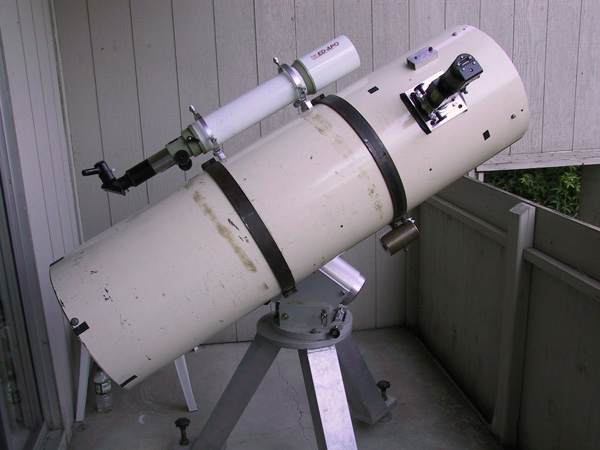
The entire setup looks like this.
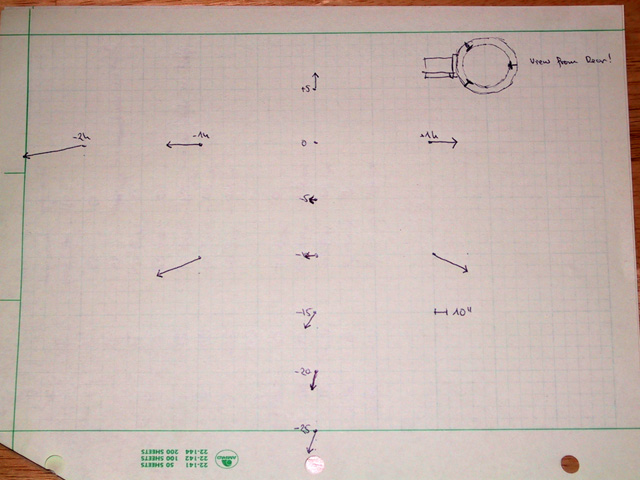
An analysis of the dependence of flexure from the location on the sky where the scope was pointing to shows an 'overshooting' of the main scope. It always point a little farther into the direction that the scope was turned to than the guide scope. The following graph displays the error.
I originally looked at the mirror cell, but discarded the idea. At a second look I decided to measure the position of the main mirror's back with respect to the rear end of the tube (actually the strut of the mirror cell where it attaches to the tube)
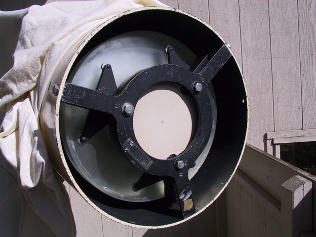
Here is a look at the mirror cell.
This is a close up of the strut to the tube wall and the support for the back of the mirror.
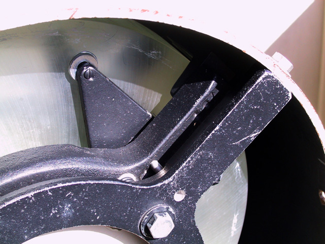
To this strut I attached i holder for a 1 um micrometer.
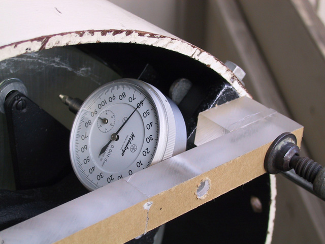
For the same positions for which I logged the displacement of the guide stars I measured the deviation of the position of the rear of the mirror. Here is plot of the numerical analysis of the flexure measurements.
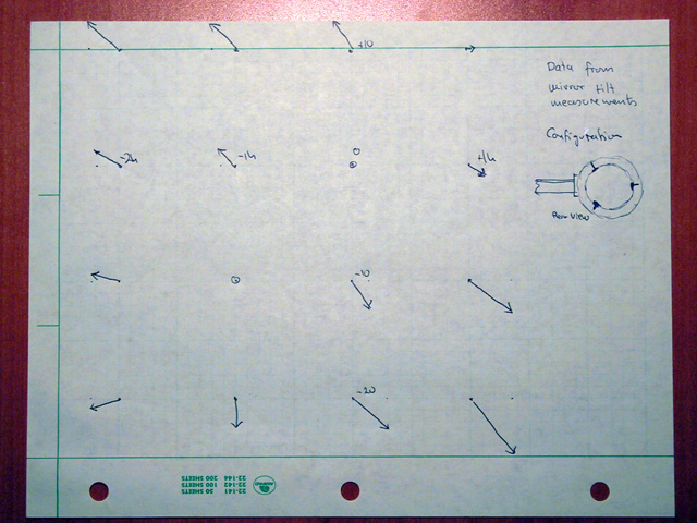
Compare again with the error determined from guide scope displacement measurements.
The triangles that make up the support for the mirror seem to be too thin to carry the weight without flexing. As a result I decided to replace them by thicker aluminum discs. The disc not necessarily give the same configuration than the triangles. It remains to be seen if any mirror flexure can be detected from the slightly different support mechanics.
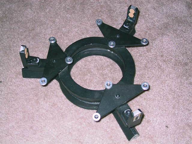
Here in the original configuration of the mirror cell as it comes from K. Novak.
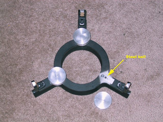
Here is the comparison between the original triangles and the replacement discs.
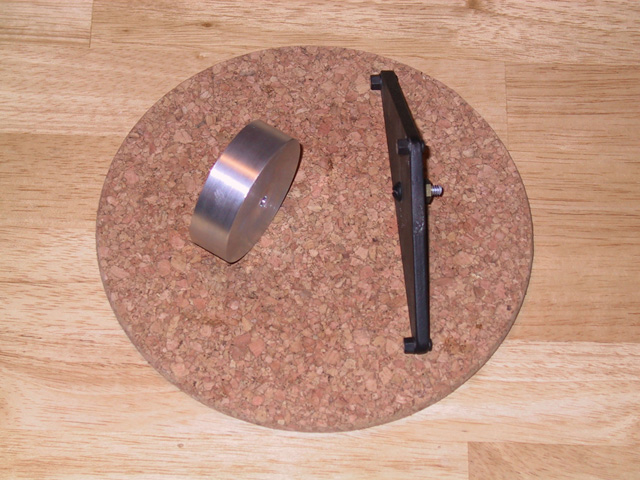
It is pretty obvious that the discs will certainly not flex. It is interesting to note the quite thick nylon pads on the triangles. I have no idea why they are so thick. More stability could easily be added to the triangles if they were made thicker. The support for the discs is a hardened steel ball from ball bearings 1/4 inch in diameter set in a hole in the cast aluminum main body of the support structure.
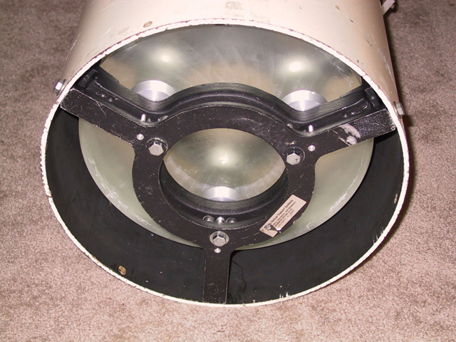
With this setup the completely mounted main mirror looks like that.
Next I want to reassess the differential flexure between the two tubes. I hope the error has now gotten smaller.
Images and processing Gert Gottschalk, drgert1@yahoo.com